|
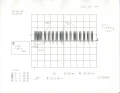
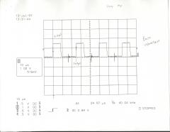
I have always been interested in computer and remote control. Somehow I imagined that building a project to encode and decode the infrared codes used by commercial electronic devices would be very difficult. I'd get there one day, I thought. I knew that my first step would be to look at the signal in a handheld remote that was used to drive the infrared LED. While working a Sykes Datatronics one night, I got that chance. I used a digital storage scope and saw it would all be relatively easy after all. I saw that the waveform was highly repetitive and easy to reproduce. I went home that night and designed my first infrared remote project. My first project was pretty much a proof of concept type project. I took the decoded bit stream I got from the digital storage scope and programmed it into a 2764 EPROM. I then connected the address pins of the EPROM to a 12 bit counter (the CD4040), and used just one data bit to drive a transistor and then the infrared LED. The infrared code I used was the channel up code for my television. I built the circuit so that it would continually cycle through this code with a brief delay in between. I saw from prolonged testing that my initial design was over 95% accurate.
My second infrared design, pictured on the right, used about 12 TTL ICs, and two EPROMs to store the codes from my stereo, TV and VCR. I could connect it to my computer and have control of all three of these systems.
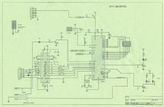
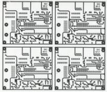
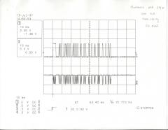
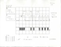
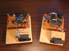
Over the years I would revisit infrared remote control projects several times. I finally got around to building one based on an 8051 family microcontroller sometime around 1992. I discovered the Atmel AT89S8252 and instantly fell in love with it. It had 8 KB of in circuit reprogrammable FLASH, 2 KB of EEPROM, and all of the other features of the basic 8051. I built two infrared transceivers using the 8252, see image below. This project could both decode and encode remote control codes. It was essentially a computer controlled learning remote control. I wrote the entire program in assembly language, but unfortunately ran out of program space before I got to implement all of the features I wanted. I decided to conserve program space I would only implement two of the three major encoding schemes (space and pulse encoding). The figures below actually show the output from an IR demodulator. I used the Sharp GP1U5X, very similar to this one.

Space EncodingBit values are determined by the length of the spaces between the pulses. |

Pulse EncodingBit values are determined by the length of the pulses. |

Shift EncodingBit values are determined by the direction of the transition. |
|
I put this design through plenty of testing. I would set one up in my attic with a VCR and have the controlling computer repeatedly command the circuit to send out the channel up code, and increment a counter each time. At first I would check how things were going every other minute or so, then every five minutes, then every hour ... I saw that either the system was failing an exact multiple of the number of channels the VCR had, or it was perfect. It would run for 6 hours and only miss one or two. I figured I could run the system for many days and get accurate test results as long as I checked up on it every 12 hours or so. In doing this prolonged type of testing, I found my design to be over 99.98% accurate.
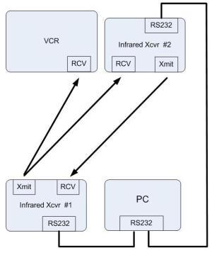
I came up with another innovative test (see "IR Test Setup" diagram to right). I would setup one of the IR transceivers (#1) about 12 feet in front of a VCR, and then another (#2) one on top of the VCR. I made sure that the IR output from the transceiver on top of the VCR would not be seen by the VCR. I then set up both transceivers in a new test mode where they would sit idle until they received an IR transmission. They'd wait ten seconds, then transmit the code they just received. I connected a computer to both transceivers and logged the output from each.
|
I'd start the test by having the computer direct the transceiver #1 to send out the channel up code. That would be received by the VCR and transceiver #2 at the same time. The VCR would increment its channel, transceiver #2 would output a code string to the computer, and ten seconds later transmit that same code via infrared light to transceiver #1. Transceiver #1 would output a code string to the computer, and ten seconds later re-transmit that same code. Obviously, if my infrared decoding and encoding algorithms were perfect, this could go on forever, with the VCR incrementing its channel after every IR transmission from transceiver #1.
Of course, nothing's perfect and things didn't quite work that way. When I first tried this test, the channel on the VCR would increment about 12 times before the signal reproduction was so distorted that it no longer was decoded properly. Through changes to my algorithms I eventually got it to run for 24 complete iterations before the distortion was too great and it would stop working.
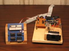
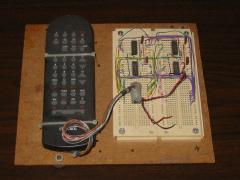
Shown below are two other things I built to test my encoding and decoding algorithms. One of them was just a pair of 10-LED bar displays that displayed diagnostic information from the transceiver. The other was a remote control that I adapted so that it could be controlled from an 8 bit I/O port. At one point I wanted to see how many times in a row my VCR could receive a transmission from an actual remote control before it failed.
|
|
