|
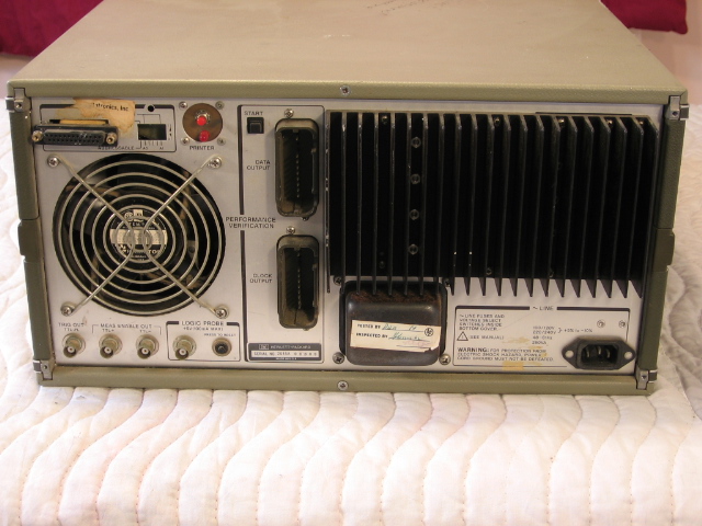
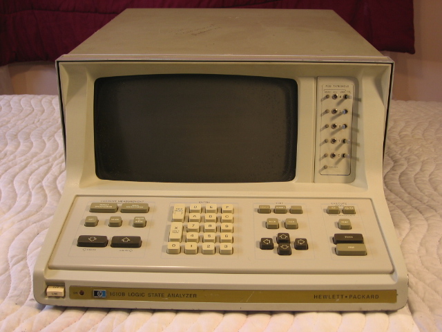
I bought a Hewlett Packard 1610b logic analyzer (shown at right) from my first employer after graduating from MCC with my Associates degree in Electronics Technology. It was a 32 bit analyzer and came with just one 8 bit pod. Although I paid only $50 for the analyzer, I ended up buying 4 more 8 bit pods for about $250. I'm not sure if I ever actually used all 32 bits ... but I did use it for several years with various projects I made with my Vic 20, Commodore 64, and Apple IIe computers. When I saw that the analyzer had one or two auxiliary slots, I began thinking up this project.
|
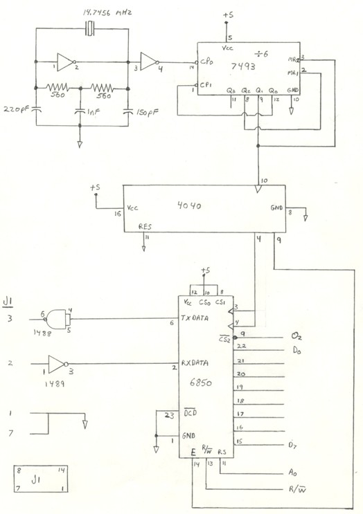
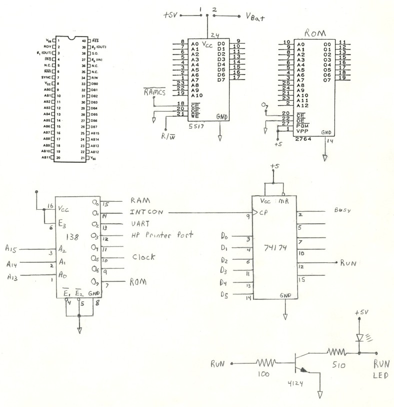
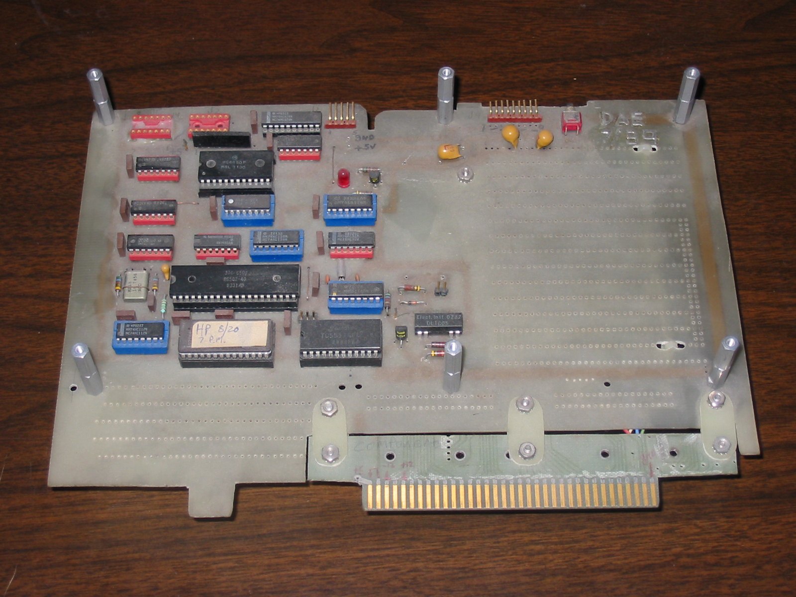
This was a board I designed and etched myself, and used the 6502 microprocessor from MOS Technology. When the "Print" button on the front of the analyzer was pressed, the text on the screen would be dumped to the printer port on the back of the logic analyzer. I re-wired the serial data cable that originally went to that printer port to go to my 6502 microprocessor board (which plugged into one of the auxiliary slots). I wrote a program, in 6502 assembly language, that would grab that text information, massage it in various ways, and then send it out another RS232 port. This was then wired to a DB25 connector on the back of the analyzer.

|
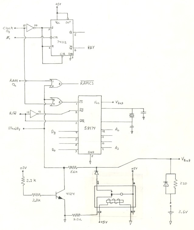
My program allowed the data which would normally be output to be changed in a variety of ways. This was configurable through menus accessible via the terminal I connected (via a RS232 switch box) to the new RS232 port on the rear of the analyzer. For example, the data could be output in a variety of formats, hex, decimal, binary, etc. I also added a few dis-assemblers (for the 6502, 8051, and the 7041/CTS256A-AL2 ) to the program, so that the data could be converted to assembly language mnemonics. By using this board I was able to enhance the functionality of the logic analyzer by allowing the data to be displayed in ways that were not originally possible. The circuit also had a real time clock, the MM58174A from National Semiconductor, so that a time/date stamp could be added to each print out.
If I remember correctly, this project was one of my first microprocessor projects.